
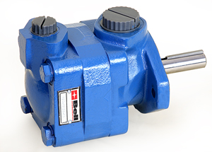
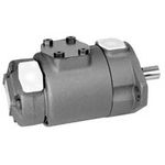
Fixed Displacement Vane Pumps


[!–VMCatalog{div id=”product-tabs”}–]
[!–VMCatalog{div id=”tab-1″}–]
[!–VMCatalog{/div}–]
[!–VMCatalog{div id=”tab-2″}–]
Performance
These cost-effective pumps provide volumetric efficiencies of more than 90% and sound levels as low as 62 dB(A) with operating pressure to 210 bar. On site repair via the replaceable pump cartridge reduces downtime to increase productivity.
[!–VMCatalog{div style=”margin-top: 20px;”}–]
General Description
Intravane pumps provide longer life, increased productivity and application versatility. Extremely low sound levels are compatible with the most demanding industrial applications. Compact size and of service allow maximum equipment design flexibility. Pumps are available in single and double configurations.
[!–VMCatalog{/div}–]
[!–VMCatalog{div style=”margin-top: 20px;”}–]
Features and Benefits
- High operating pressure capabilities in compact packages provide high power to weight ratios and lower installed coats.
- Low noise characteristics inherent in intravane design enhance operator comfort.
- Twelve vane system provides low amplitude flow pulsations resulting in low system noise characteristics.
- Hydraulic balancing, designed to prevent internally-induced radial shaft and bearing loads, provides long life.
- Double pumps arrangements save installation space and cost by eliminating double shaft extension electric motors or by reducing the number of motors and drive coupl¬ings.
- Thirty-one flow displacements and high operating pressure capability provide optimum selection and single-source capability for your complete range of flow and pressure requirements.
- Factory tested cartridge kits provide new pump performance upon installation.
- The cartridge kit design offers fast and efficient field serviceability. The cartridge is independent of the drive shaft, allowing for easy change of flow capacity and servicing without removing the pump from its mounting.
[!–VMCatalog{/div}–]
[!–VMCatalog{/div}–]
[!–VMCatalog{div id=”tab-3″}–]
Hydraulic Fluids
Use antiwear industrial hydraulic oils or automotive crankcase oils having letter designations SC,SD,DE or SF with viscosity grades of 32 to 68 cSt at 40°C(140°F) Preferred viscosity at rated speed and pressures:Minimum 13 cSt (70 SUS) Maximum 54 cSt(70 SUS) Minimum 49° C(12(f F) Maximum C(12(f F).
[!–VMCatalog{div style=”margin-top: 20px;”}–]
Cold Stares
When operating SAE 10W oil in the 860 to 54 cSt(400 to 251 SUS) range,the speed and pressure should be limited to 50% or less of their respective rated values until the system has warmed up.Extreme caution must be used when starting units when fluid viscosity’s are greater than 860 cSt(4000 SUS).Care should be exercised to warm up the entire system,including remote cylinders and motors.
[!–VMCatalog{/div}–]
[!–VMCatalog{div style=”margin-top: 20px;”}–]
High Temperatures
Viscosities must not be less than the respective minimum values for each series of pumps.Temperatures should not exceed 99 C(210 F) because the expectancy of cartridge kite and elastomers will decrease.
[!–VMCatalog{/div}–]
[!–VMCatalog{div style=”margin-top: 20px;”}–]
Water-in-oil Emulsions
Water-in-oil emulsions may be used.However,they require careful selection and monitoring of the fluid. Soluble oil-in-water solutions are not recommended.
[!–VMCatalog{/div}–]
[!–VMCatalog{div style=”margin-top: 20px;”}–]
Synthetic Fire Resistant Fluids
Phosphate esters and their blends with operating viscosity of the petroleum oil described above may be used.These fluids are generally compatible with fluorocarbon and silicone elastomers.Add F3 prefix to the model code for special seals.
[!–VMCatalog{/div}–]
[!–VMCatalog{div style=”margin-top: 20px;”}–]
Filtration Requirements
For satisfactory service life of components,use full flow filtration to provide fluid cleanliness conforming to ISO code 18/15 or better.
[!–VMCatalog{/div}–]
[!–VMCatalog{div style=”margin-top: 20px;”}–]
Drive Data
Pumps are assembled for CW or CCW rotation.Right hand or clockwise rotation and left hand or counterclockwise rotation is viewed from the shaft end.
Inlet and outlet ports remain the same regardless of the direction of shaft rotation.Assembly change of internal parts is necessary,when change of shaft rotation is required.
[!–VMCatalog{/div}–]
[!–VMCatalog{div style=”margin-top: 20px;”}–]
Pump Drive
Direct coaxial drive is recommended.If drives imposing radial and/or axial shaft loads are considered.
[!–VMCatalog{/div}–]
[!–VMCatalog{div style=”margin-top: 20px;”}–]
Air Bleed
At the time of first-starting,if the pump does not immediately prime,air should be bled from the pump delivery line.This may be accomplished by loosening a connection in the delivery line close to the pump until oil flows -indicating the pump has primed.An air bleed valve is available for this purpose.
[!–VMCatalog{/div}–]
[!–VMCatalog{div style=”margin-top: 20px;”}–]
Caution: No Case Drain
The pump is drained internally into its inlet.System pressure at the pump inlet connection may not exceed 1.4bar(20PSI).
[!–VMCatalog{/div}–]
[!–VMCatalog{div style=”margin-top: 20px;”}–]
Caution:Low Outlet Pressure
Do not run a pump with the outlet pressure lower than the inlet pressure.This causes operating noise and vane instability.
[!–VMCatalog{/div}–]
[!–VMCatalog{div style=”margin-top: 20px;”}–]
Start-up(Commissioning) Procedure
- Make sure the reservoir and circuit are clean and free of dirt/debris prior to filling with hydraulic fluid.
- Fill the reservoir with filtered oil and fill to a level sufficient enough to prevent vortexing at suction connection to pump inlet.lt is goodpractice to clean up the system by flushing and filtering using an external slave pump.
- Before starting the pump,fill with fluid trough one of the ports.This is particularly important if the pump is above the fluid level of the reservoir.
- When initially starting the pump,bleed all trapped air from the system.This can be accomplished by loosening the pump outlet fittings or connections before starting the pump or by using an air bleed valve.AII inlet connections must be tight t prevent air leaks.
- Once the pump is stated it should prime within a few seconds.If the pump dose not prime,check to make sure that ther< are no restrictions between the reservoir and the inlet to pump,and that there are no air leaks in the inlet line and connections.Also check to make sure that trapped air can escape at the pump outlet.
- After the pump primed,tighten the loose outlet connections,then operate for five to ten minutes unloaded to remove all trapped air from the circuit.
- If reservoir has a sight gage,make sure the fluid is clear-not milky.
- Add fluid to the reservoir to bring it up to the proper fill level.
[!–VMCatalog{/div}–]
[!–VMCatalog{/div}–]
[!–VMCatalog{/div}–]