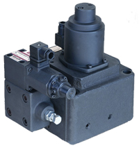
EFBG-03 Proportional Electro-Hydraulic Relief and Flow Control Valves
[!–VMCatalog{div class=”product-image float-left;” style=”width:40%;”}–]
[!–VMCatalog{div style=”margin-top: 15px;text-align: justify;”}–]
[!–VMCatalog{/div}–]
[!–VMCatalog{/div}–]
[!–VMCatalog{div class=”ordering-code” style=”width:55%;”}–]
Note :
1. Pipe the return direct back to tank on its own below the oil level for minimum back pressure.
2. The specification chart above relates to performance achievable using HNC standard electronic controller type HNC-4075, HNC-1085 and a pump flow of 125lpm (EFBG-03), 250lpm (EFBG-06), 500lpm (EFBG-10) at oil temperature 45°C / 113°F and viscosity 45 cSt.
[!–VMCatalog{/div}–]
[!–VMCatalog{div class=”clear-fix”}/–]
[!–VMCatalog{div id=”product-tabs”}–]
[!–VMCatalog{div id=”tab-1″}–]
Dimensions
[!–VMCatalog{div style=”margin-top: 30px;”}–]
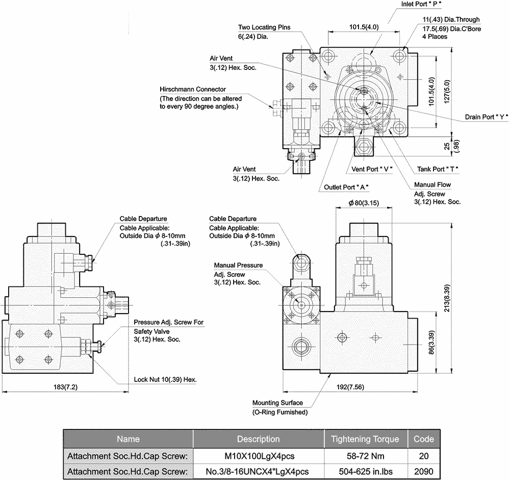
EFBG-03 Proportional Electro-Hydraulic Relief and Flow
Control Valves (40Ω-10Ω Series)
![]()
[!–VMCatalog{/div}–]
[!–VMCatalog{div style=”margin-top: 30px;”}–]
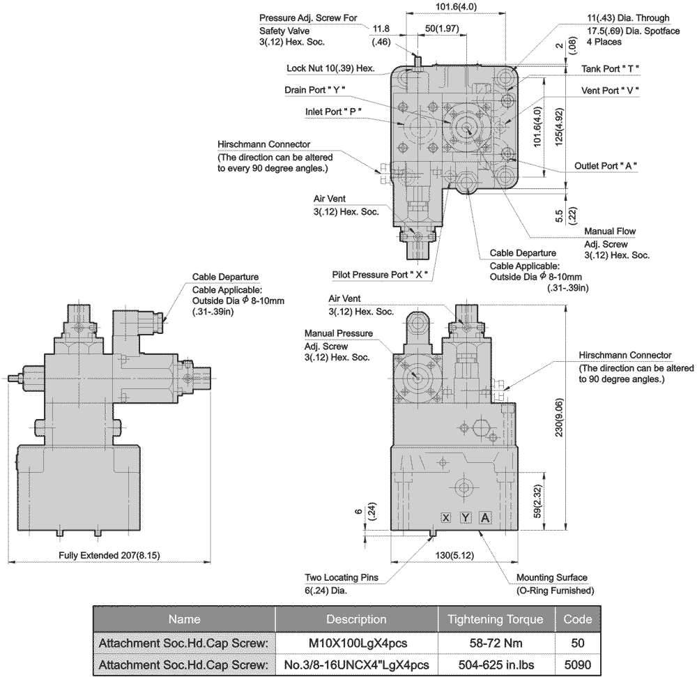
EFBG-03 Proportional Electro-Hydraulic Relief and Flow
Control Valves (10Ω-10Ω Series)
[!–VMCatalog{/div}–]
[!–VMCatalog{/div}–]
[!–VMCatalog{div id=”tab-2″}–]
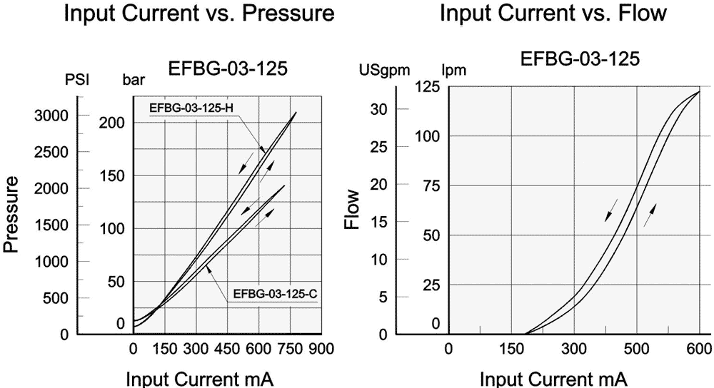
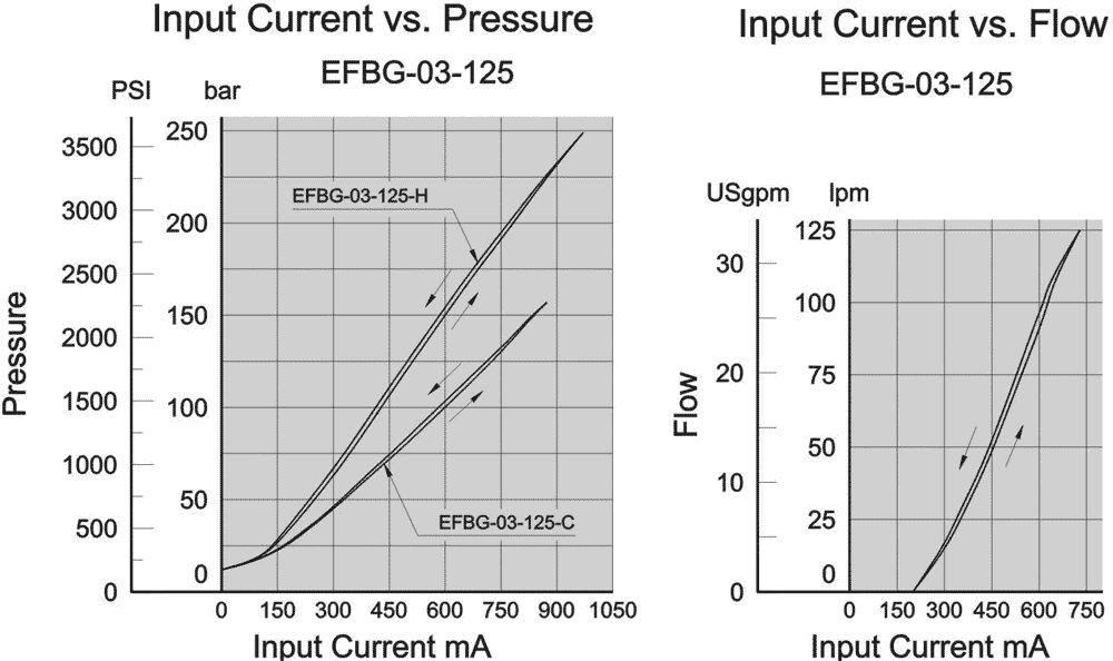
Performance Curves
[!–VMCatalog{div style=”margin-top: 30px;”}–]
EFBG-03 Proportional Electro-Hydraulic Relief and Flow Control Valves (40Ω-10Ω Series)
[!–VMCatalog{/div}–]
[!–VMCatalog{div style=”margin-top: 30px;”}–]
EFBG-03 Proportional Electro-Hydraulic Relief and Flow Control Valves (10Ω-10Ω Series)
[!–VMCatalog{/div}–]
[!–VMCatalog{/div}–]
[!–VMCatalog{div id=”tab-4″}–]
Operating Data
[!–VMCatalog{div style=”text-align: justify;”}–]
Position For Installation:
To install the valve correctly mount with “bleed” up-wards in order to eliminate air and reduce the risk of air entrapment.
Elimination Of Air(Air Vent)
Set the pilot control pressure to 29.4bar(420PSI) and open the bleed screw to eliminate the air.Lock the bleed screw when all air bubbles have been eliminated.The above will ensure a stable adjustable pressure control and a smooth adjustable speed control.
Manual Over-Ride
It is possible to set the both control pressure control and flow control manually for commissioning and trouble shooting purposes.
Drain
Pipe the return back to tank below the oil level.lt is essential that the back pressure is kept to a minimum and does not exceed 2 bar(29PSI).
[!–VMCatalog{/div}–]
[!–VMCatalog{/div}–]
[!–VMCatalog{div id=”tab-5″}–]
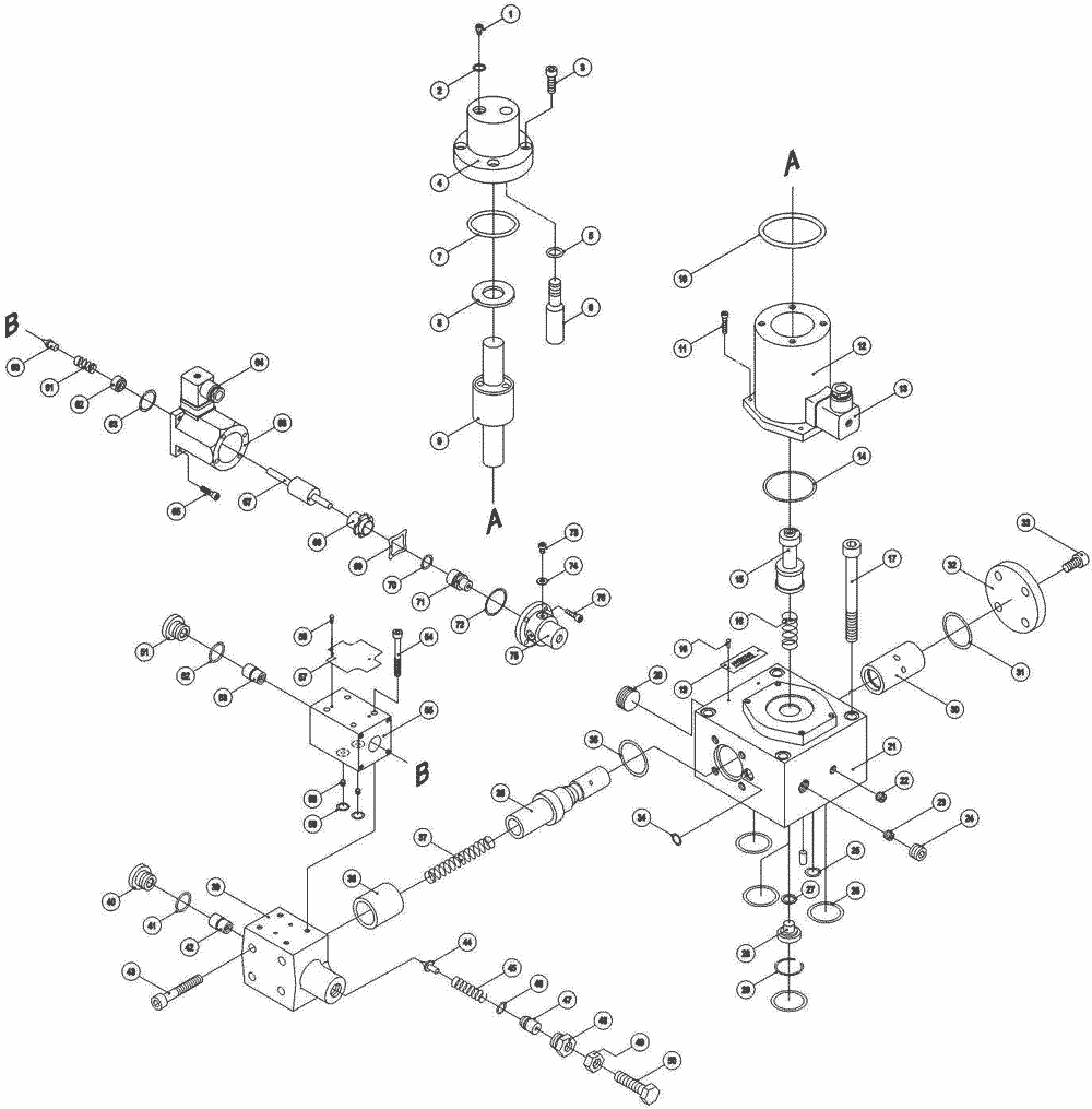
Assembly
[!–VMCatalog{div style=”margin-top: 30px;”}–]
EFBG-03 Proportional Electro-Hydraulic Relief and Flow Control Valves (40Ω-10Ω Series)
[!–VMCatalog{/div}–]
[!–VMCatalog{/div}–]
[!–VMCatalog{div id=”tab-6″}–]
Ratings
| Model No. |
EFBG-03-125-C-20 40Ω-10Ω Series
|
EFBG-03-125-C-20 10Ω-10Ω Series
|
|
|---|---|---|---|
|
Max. Operating Pres. bar (PSI) |
206 (2987) | 250 (3600) | |
|
Max. Flow lpm (USgpm) |
125 (33) | ||
|
Metred Flow Adjustment Range lpm (USgpm) |
1-125
(0.26-33) |
||
| Flow
Controls |
Rated Current
mA |
750 | 800 |
| Coil Resistance
Ω |
40 | 10 | |
| Valve Internal Resistance
(A→B) bar (PSI) |
5 (72.5) | ||
| Hysteresis
% |
< 7 | ||
| Repeatability
% |
< 1 | ||
| Pressure
Controls |
Pres. Adj. Range
bar (PSI) |
C : 8~140(116~2030)
H : 10-206(145~3000) |
C : 8~140(116~2030)
H : 10-250(145~3600) |
| Rated Current
mA |
C : 700
H : 750 |
C : 820
H : 880 |
|
| Coil Resistance
Ω |
10 | ||
| Hysteresis
% |
< 3 | ||
| Repeatability
% |
< 1 | ||
| Weight
kg(lbs.) |
18 (39.6) | 16 (35.3) | |
[!–VMCatalog{/div}–]
[!–VMCatalog{/div}–]


