
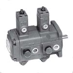
PVDF – Double Pumps


[!–VMCatalog{div class=”product-image float-left” style=”width:30%; margin-top:140px; margin-left:50px”}–]
[!–VMCatalog{/div}–]
[!–VMCatalog{div class=”ordering-code” style=”width:50%;”}–]
Ordering Code
| PVF | -3 | -70 | -3 | -70 | -11 | ||||
|---|---|---|---|---|---|---|---|---|---|
| Series No. | Shaft end Pump | Cover end Pump | Design No. | ||||||
| Outlet Flow (lpm) at 3.5 bar, 1800 rpm | Operating Pressure range (bar) | Outlet Flow (lpm) at 3.5 bar, 1800 rpm | Operating Pressure range (bar) | ||||||
| PDVF
Flange Mounting |
Code | Outlet Flow (lpm) | Code | Pressure Range | Code | Outlet Flow (lpm) | Code | Pressure Range | 11: PT(Rc) |
| 3 | 30 lpm | 20 | 8 ~ 20 bar | 3 | 30 lpm | 20 | 8 ~ 20 bar | ||
| 4 | 40 lpm | 35 | 15 ~ 35 bar | 4 | 40 lpm | 35 | 15 ~ 35 bar | 1180: PF(G) | |
| Factory Setting Qmax. | 55 | 30 ~ 55 bar | Factory Setting Qmax. | 55 | 30 ~ 55 bar | ||||
| 70 | 55 ~ 70 bar | 70 | 55 ~ 70 bar | 1190: NPT | |||||
| Factory Setting Pmin. | Factory Setting Pmin. | ||||||||
[!–VMCatalog{/div}–]
[!–VMCatalog{div class=”clear-fix”}/–]
[!–VMCatalog{div id=”product-tabs”}–]
[!–VMCatalog{div id=”tab-1″}–]
Operating Data
[!–VMCatalog{div style=”margin-top: 10px;margin-bottom: 20px;”}–]
ROTARY DIRECTION
Clockwise rotation viewed from shaft end is standard.
[!–VMCatalog{/div}–]
[!–VMCatalog{div style=”margin-bottom: 20px;”}–]
FLUIDS PERMISSIBLE
When working pressure lower than 70 bar, hydraulic oil with a viscosity ranging from 30~50 cSt(ISO VG32). When working pressure higher than 71 bar .hydraulic oil with a viscosity ranging from 50-70 cSt(ISO VG68) at 40°C is recommended.(ISO VG32) at 40 °C is recommended.
[!–VMCatalog{/div}–]
[!–VMCatalog{div style=”margin-bottom: 20px;”}–]
DRAIN PORT PIPING
Drain connection must be piped directly to tank and below the oil level with a back pressure not exceed 0.3 bar.
[!–VMCatalog{/div}–]
[!–VMCatalog{div style=”margin-bottom: 20px;”}–]
OIL TEMPERATURE RANGE
Oil temperature range should be between 15-60°C for continuous operation and should be higher than 7°C at starting.
[!–VMCatalog{/div}–]
[!–VMCatalog{div style=”margin-bottom: 20px;”}–]
ALIGNMENT AND INSTALLATION OF PUMP
The shaft alignment for pump and electric motor shall be limited to 0.05mm TIR. and 1 degree angular error.
[!–VMCatalog{/div}–]
[!–VMCatalog{div style=”margin-bottom: 20px;”}–]
INLET PORT PRESSURE
Inlet port pressure should be -0.3 bar to +0.3 bar.
[!–VMCatalog{/div}–]
[!–VMCatalog{div style=”margin-bottom: 20px;”}–]
FLOW ADJUSTMENT
The flow will be reduced when the flow adjusting screw is turned clockwise and increased when anti-clockwise.
[!–VMCatalog{/div}–]
[!–VMCatalog{div style=”margin-bottom: 20px;”}–]
PRESSURE ADJUSTMENT
The pressure will be increased when the pressure adjusting screw is turned clockwise and reduced when anti-clockwise.
P-Q CHARACTERISTICS ( EX-WORK SET ) Flow setting:The max. flow as catalogue shown. Pressure setting:The min. operating pressure range.
[!–VMCatalog{/div}–]
[!–VMCatalog{div style=”margin-bottom: 20px;”}–]
SLIDE SCREW
The slide screw is non-adjustable and set at factory. Unauthorized persons cannot tamper with the desired setting.
[!–VMCatalog{/div}–]
[!–VMCatalog{div style=”margin-bottom: 20px;”}–]
CAUTIONS FOR STARTING
Start up the pump under No-Load condition and repeat to start and stop the motor several times to extract the air from inside of the pump and piping.Then keep a 10 minutes continuous running for a better de-airing.
[!–VMCatalog{/div}–]
[!–VMCatalog{div}–]
PEAK-PRESSURE
The peak pressure is 140 bar for code * 2 & * 3,and 210 bar for A4 & A5.
[!–VMCatalog{/div}–]
[!–VMCatalog{/div}–]
[!–VMCatalog{div id=”tab-3″}–]
Assembly

Parts List:
[!–VMCatalog{div style=”width: 49%; margin-right: 1%; float: left;”}–]
| No. | Part Name | Specification | Quantity |
|---|---|---|---|
| 1 | Retainer Ring | R42 | 1 |
| 2 | Shaft Seal | TCV 224211 | 1 |
| 3 | Pump Body | 1 | |
| 4 | Piston | 2 | |
| 5 | Piston | 2 | |
| 6 | O-Ring | 1A-P5 | 2 |
| 7 | O-Ring | 1A-P22 | 2 |
| 8 | Thrust Screw | 2 | |
| 9 | Socket Set Screw | M12xP1.75x25L | 2 |
| 10 | Hexagon Nut | M12xP1.75 | 2 |
| 11 | Slide Screw | 2 | |
| 12 | O-Ring | 1A-P14 | 2 |
| 13 | Hexagon Nut | M16xP1.0 | 2 |
| 14 | Cap | 2 | |
| 15 | Piston | 2 | |
| 16 | Spring | 1 | |
| 16-1 | Spring | 1 | |
| 17 | Spring Retainer | 2 | |
| 18 | O-Ring | 1A-P22A | 2 |
| 19 | Cover | 2 | |
| 20 | Socket Head Cap Screw | M6xP1.0x20L | 8 |
| 21 | Socket Set Screw | M10xP1.5x35L | 2 |
| 22 | Hexagon Nut | M16xP1.5 | 2 |
| 23 | Spring Pin | ø4×10 | 2 |
| 23-1 | Spring Pin | ø4×10 | 4 |
| 24 | Straight Pin | ø4×10 | 4 |
[!–VMCatalog{/div}–]
[!–VMCatalog{div style=”width: 49%; float: left;”}–]
| No. | Part Name | Specification | Quantity |
|---|---|---|---|
| 25 | Engine Bush | DIADO(Japan)DD2225 | 1 |
| 25-1 | Engine Bush | DIADO(Japan)DD2225 | 2 |
| 26 | Port Plate | 2 | |
| 27 | Rotorshaft | 1 | |
| 28 | Vanes | 26 | |
| 29 | Cam Ring | 1 | |
| 29-1 | Cam Ring | 1 | |
| 30 | Thrust Plate | 2 | |
| 31 | O-Ring | AS568-030 | 2 |
| 32 | Endless Back-up Ring | 2 | |
| 33 | O-Ring | AS568-035 | 2 |
| 34 | Endless Back-up Ring | 2 | |
| 35 | O-Ring | 1A-S85 | 2 |
| 36 | Pump Body | 1 | |
| 37 | Woodruff Key | No. 406 | 1 |
| 38 | Rotor | 1 | |
| 39 | Cover | 1 | |
| 40 | Socket Head Cap Screw | M10xP1.5x10L | 4 |
| 41 | Name Plate | 1 | |
| 42 | Fixing Screw | 3 | |
| 43 | Woodruff Key | No.608 | 1 |
| 44 | Spring Washer | M10 | 4 |
| 45 | Socket Head Cap Screw | M10xP1.5x30L | 4 |
♦ 44 ~ 45 are Accessories.
♦ 4 & 4-1; 26 & 26-1 is same kits (Without spring 16-1)
♦ 23 & 23-1; 28 & 28-1 is same kits 9Without Cam-ring 29-1)
[!–VMCatalog{/div}–]
[!–VMCatalog{div class=”clear-fix”}/–]
[!–VMCatalog{/div}–]
[!–VMCatalog{div id=”tab-4″}–]
Dimensions

[!–VMCatalog{/div}–]
[!–VMCatalog{/div}–]