
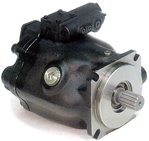
HV Series Variable Volume Piston Pumps


[!–VMCatalog{div class=”product-image float-left” style=”width: 38%;”}–]
[!–VMCatalog{/div}–]
[!–VMCatalog{div class=”ordering-code” style=”width:60%;” }–]
Features:
- Combining special internal designs and strict engineering disciplines has reduced noise level to new lows in whole pressure zones.
- Depending on variety of application needs multiple optional unique control methods are available, it does not only reduce a number of unnecessary hoses, pipes and control valves but also increase efficiency and save horsepower, and cost.
- Less capacity reservoirs can be selected and applied because of performances of low pressure loss and less head generation.
- Wide application ranges:it is very suitable for machine tools, plastic injection molding machines, forging machines and other industrial machines etc..
- Mounting flanges are made to SAE A or B 2-bolt (V15.18, 38 types) and SAE-C 2 & 4-bolt (HV-50.HV-70 types).
[!–VMCatalog{/div}–]
[!–VMCatalog{div class=”clear-fix”}/–]
[!–VMCatalog{div id=”product-tabs”}–]
[!–VMCatalog{div id=”tab-7″}–]
Ordering Code
| HV | 38 | A | 4 | R | S | F | -20 |
|---|---|---|---|---|---|---|---|
| Series No | Displacement
cc/rev (in3/rev) |
Control Type | Pressure Compensating Range
bar(PSI) |
Rotation | Port Position | Mounting | Design No. Shaft Option Flange Option |
| HV
Variable Volume Piston Pump |
15(0.9)
18(1.1) 23(1.4) 38(2.3) 50(3.1) 70(4.3) |
Standard | 1:8~70(115-1000)
2:15~140(210-2000) 3:20~210(280-3000) 4:20~250(280-3500) |
R:Clockwise(CW)
L:Counter Clockwise(CCW) Viewed from Shaft End |
S:Side port
R:Axial port |
F:FlangeMounting
L:Foot Mounting |
20: PT(Rc) Flange kits, Straight Key
2080:PF(G) Flange Kits,Straight Key 2090:NPT Flange Kits,Straight Key 30:PT(Rc) Flange Kits,SAE B (13 Tooth) 3080:PF(G) Flange Kits,SAE B(13 Tooth) 3090:NPT Flange Kits,SAE B (13 Tooth) |
| A:Pressure Compensating(manual) | |||||||
| Option | |||||||
| B:Pressure Compensating Type Pilot | |||||||
| (Remote Control) | |||||||
| C:TwoPressure-Two FLow | |||||||
| DV
Variable Volume Piston Pump |
15(0.9)
18(1.1) 23(1.4) 38(2.3) |
Control Type | |||||
| D:Solenoid Cut-Off Control Type | |||||||
| Control Type | |||||||
| E:Two Pressure Cut-Off Control Type | |||||||
| F:Two Pressure,Two Flow Control | |||||||
| Type by Solenoid Valve | |||||||
| G:Two Pressure,Two Flow Control | |||||||
| Type by Solenoid Valve | |||||||
| H:Power Maching Control | |||||||
| HL:Load Sensing Compensator | |||||||
| HJ:Electro-Hydraulic Proportional | |||||||
| Load Sensing Type | |||||||
| DV Series available in A,B,C,D,H and | |||||||
| HL type only |
[!–VMCatalog{/div}–]
[!–VMCatalog{div id=”tab-1″}–]
Standard Type
| Symbol | Size | External View | Performance Curve | Hydraulic Circuit | Description |
|---|---|---|---|---|---|
| A | 15 |  |
 |
 |
Pressure Compensating Type(Manual)
When the pressure reaches the value set with the compensator. The flow is reduced automatically and the set pressure is maintained. The Pressure and flow are controlled automatically |
| 18 | |||||
| 23 | |||||
| 38 | |||||
| 50 | |||||
| 70 | |||||
| 100 |
Option


[!–VMCatalog{/div}–]
[!–VMCatalog{div id=”tab-2″}–]
Operating Data
[!–VMCatalog{div style=”margin-top: 20px”}–]
Fluid Recommendations
In case hydraulic pressure is under 70 bar, use hydraulic oil which is corresponding to ISO VG32-60 in viscosity grade or wear resisting hydraulic oil.
In case hydraulic pressure is over 70 bar, use wear resisting hydraulic oil which is corresponding to ISO VG32-68 in viscosity grade.
In case hydraulic pressure is under 70 bar, use hydraulic oil which is corresponding to ISO VG32-60 in viscosity grade or wear resisting hydraulic oil.In case hydraulic pressure is over 70 bar, use wear resisting hydraulic oil which is corresponding to ISO VG32-68 in viscosity grade.
[!–VMCatalog{/div}–]
[!–VMCatalog{div style=”margin-top: 20px”}–]
Viscosity and Operating Temperature
Oil viscosity ranging from 15 cStto 400 cSt and oil temperature from 0°C to 60 °C are recommended.
[!–VMCatalog{/div}–]
[!–VMCatalog{div style=”margin-top: 20px”}–]
Istallation and Mounting
Eccentricity between the driving shaft and pump shaft should be under 0.05 TIR, and operate the pump in such a way that the pump shaft is not subjected to orthogonal force. If centering between the driving shaft and pump shaft is incorrect, the bearing and oil seal may be damaged, noise and vibration may occur, which cause trouble with the pump.
Avoid driving the pump in the lateral direction by belt, chain or gears. (This may cause noise and damage the bearing.)
The pump can be operated with its shaft mounted perpendicularly.
[!–VMCatalog{/div}–]
[!–VMCatalog{div style=”margin-top: 20px”}–]
Piping Work
Use parallel thread pipe joints for the suction inlet and discharge outlet. Do not use taper thread piping joints or air may intrude or abnormal noise be produced.
In case where steel pipes are used, lay the piping with care so as not to put force on the pump.
Eccentricity of a pump being forced by piping may cause seriors trouble with noise.
[!–VMCatalog{/div}–]
[!–VMCatalog{div style=”margin-top: 20px”}–]
Drain Piping
Lay the drain piping independently not joined with other return lines, in such a way that the pump internal pressure is under 0.35 bar.
Lay the oil return piping under the oil level of the tank and as far as possible from suction piping, (refer under table )
[!–VMCatalog{/div}–]
[!–VMCatalog{div style=”margin-top: 20px”}–]
Start-Up
Before starting the pump, fill the pump case with hydraulic oil using the drain charging port on the pump body.
Do not operate the pump at full speed right away. Instead, turn the motor input switch on and off several times so as to extract air from the piping, then operate it continuously.
At the start, be sure to reduce the pressure or operate it unloaded.
[!–VMCatalog{/div}–]
[!–VMCatalog{div style=”margin-top: 20px”}–]
Shaft Rotation
Shaft rotation is clockwise viewed from the end of pump shaft. In case revolution is required, indicate it by Model No.
[!–VMCatalog{/div}–]
[!–VMCatalog{div style=”margin-top: 20px”}–]
Suction Pressure
Adjust suction pressure to within – 125mmHg.
High suction pressure may cause cavitation, damage of parts, noise and vib- ratior which greatly shorten the life of pumps.
[!–VMCatalog{/div}–]
[!–VMCatalog{div style=”margin-top: 20px”}–]
Filration
Deterioration of the hydraulic oil may cause trouble with the pump and shorten its life. Carefully control the quality of the oil so as to maintain the deterioration of the oil within Grade NAS 9.
Be sure to attach a suction filter of 150 mesh to the suction side and a line filter of 25 to the return line of the discharge side.
[!–VMCatalog{/div}–]
[!–VMCatalog{div style=”margin-top: 20px”}–]
Max. Working Pressure
Operation period at maximum working pressure should be under 10% of one cycle and the retaining period should be under 6 seconds.
[!–VMCatalog{/div}–]
[!–VMCatalog{/div}–]
[!–VMCatalog{div id=”tab-3″}–]
Assembly

Ordering Code -HV Piston Pumps Cartridge Kits
| HV | 38 | R | KW | Detail Part No. and Q’ty |
|---|---|---|---|---|
| Series No. | Displacement | Rotation | Kits Code | |
| Variable
Volume Piston Pump |
15 cc/rev | R:
Clockwise L: Counter-Clockwise |
KT | #(5)x1 |
| 16 cc/rev | KU | #(6,7)x9,(8)x1 | ||
| 23cc/rev | KV | #(4),(9),(14),(21),(28)x1#(21)x2,#(18)x3,#(6,7)x9 | ||
| 38cc/rev | ||||
| 50cc/rev | KW | #(4),(5),(8),(9),(14),(21),(28)x1#(21)x2,#(18)x3,#(6,7)x9 | ||
| 70cc/rev | ||||
| 100cc/rev | #(6,7)Size 8 x 7pcs,Size 16~36 x 9pcs,Size 46~100x11pcs | |||
Parts List:
[!–VMCatalog{div style=”width: 49%; margin-right: 1%; float: left;”}–]
| No. | Part Name |
|---|---|
| 1 | Pump Housing |
| 2 | Rear Cover |
| 3 | Shaft |
| 4 | Cylinder barrel(Cylinder block) |
| 5 | Valve pipe |
| 6 | Piston |
| 7 | Shoe |
| 8 | Shoe holder |
| 9 | Barrel holder |
| 10 | Swash plate |
| 11 | Thrust Bush |
| 12 | Seal holder |
| 13 | Gasket |
| 14 | Spring C |
| 15 | Sping S |
| 16 | Control Piston |
| 17 | Guide |
| 18 | Needie |
| 19 | Key |
| 20 | Nut |
| 21 | Retainer |
| 22 | Plug |
| 23 | Ball Bearing |
| 24 | Needle bearing |
| 25 | Oil seal |
[!–VMCatalog{/div}–]
[!–VMCatalog{div style=”width: 49%; float: left;”}–]
| No. | Part Name |
|---|---|
| 26 | Snap Ring |
| 27 | Snap Ring |
| 28 | Snap Ring |
| 29 | Oil Ring |
| 30 | Oil Ring |
| 31 | Oil Ring |
| 32 | Pin |
| 33 | Expander Plug |
| 34 | Machine Screw |
| 35 | Hexagon Socket Head Screw |
| 36 | Flow Adjusting Bolt |
| 37 | Spring Holder |
| 38 | Hexagon Socket Head Screw |
| 39 | Body |
| 40 | Spool |
| 41 | Holder |
| 42 | Plunger |
| 43 | Spring |
| 44 | Retainer |
| 45 | Pressure Adjusting Bolt |
| 46 | Nut |
| 47 | O-Ring |
| 48 | O-Ring |
| 49 | O-Ring |
| 50 | Plug |
[!–VMCatalog{/div}–]
[!–VMCatalog{div class=”clear-fix”}/–]
[!–VMCatalog{/div}–]
[!–VMCatalog{div id=”tab-4″}–]
Performance Data
CONDITIONS

NOISE LEVEL

EFFICIENCY CURVES

INPUT POWER AT FULL CUT-OFF

INPUT POWER CURVES

DRAIN CURVE

[!–VMCatalog{/div}–]
[!–VMCatalog{div id=”tab-5″}–]
Dimensions:


[!–VMCatalog{/div}–]
[!–VMCatalog{div id=”tab-6″}–]
Dimensions:

[!–VMCatalog{/div}–]
[!–VMCatalog{/div}–]