Inline Flow Control Valves
[!–VMCatalog{div class=”product-image float-left;” style=”width:25%;”}–]

[!–VMCatalog{/div}–]
[!–VMCatalog{div class=”ordering-code” style=”width:55%;”}–]
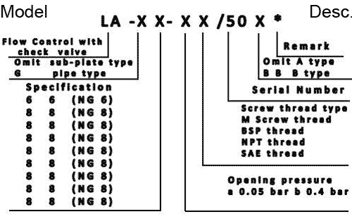
Ordering Code

[!–VMCatalog{/div}–]
[!–VMCatalog{div class=”clear-fix”}/–]
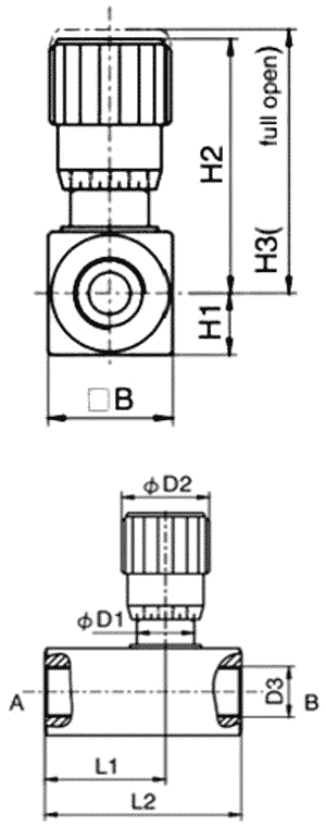
Dimensions
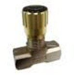
Inline Flow Control Valves

Specifications
[!–VMCatalog{div style=”margin-top: 30px;”}–]
| Specification | Model | 6 | 8 | 10 | 12 | 16 | 20 | 25 | 30 | 40 |
|---|---|---|---|---|---|---|---|---|---|---|
| Maximum Pressure (bar) | 315 | |||||||||
| Maximum Flow (l/min) | 14 | 40 | 60 | 85 | 175 | 200 | 300 | 400 | 600 | |
| Hydraulic Flow | Mineral Oil, phosphate-easter | |||||||||
| Fluid Temp. (°C) | -20~70 | |||||||||
| Viscosity (mm2/s) | 2.8~380 | |||||||||
| Cracking Pressure | a : 0.05 b : 0.4 | |||||||||
| Weight (kg) | 0.45 | 0.44 | 0.47 | 1.02 | 0.97 | 2.22 | 4.35 | 8.55 | 12.32 | |
| Symbol | ||||||||||
[!–VMCatalog{/div}–]
[!–VMCatalog{div style=”margin-top: 30px;”}–]
| Model | “B | D1 | D2 | D3 | H1 | H2 | H3 | L1 | L2 |
|---|---|---|---|---|---|---|---|---|---|
| G6 | 28 | 19.3 | 30 | G 1/8″ | 14 | 59.3 | 64.8 | 36 | 58 |
| G8 | 28 | 19.3 | 30 | G 1/4″ | 14 | 61.3 | 67.9 | 39 | 64 |
| G10 | 28 | 19.3 | 30 | G 3/8″ | 14 | 61.5 | 67.5 | 43 | 70 |
| G12 | 38 | 24.2 | 37 | G 1/2″ | 19 | 78.1 | 86.5 | 52 | 83 |
| G16 | 38 | 24.2 | 37 | G 3/4″ | 19 | 78.3 | 86.5 | 55.5 | 89 |
| G20 | 48 | 35 | 48 | G 1″ | 24 | 102.3 | 114.4 | 70.8 | 117 |
| G25 | 60 | 50 | 48 | G 1-1/4″ | 30 | 134.68 | 148.1 | 97 | 154 |
| G30 | 70 | 70 | 80 | G 1-1/2″ | 35 | 161.5 | 181.5 | 111 | 172 |
| G40 | 90 | 71 | 80 | G 2″ | 45 | 171.5 | 191.5 | 129 | 190 |
[!–VMCatalog{/div}–]


