
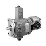
TPF – Hi-Lo Pumps


[!–VMCatalog{div class=”product-image float-left” style=”width:30%; margin-top:140px; margin-left:50px;”}–]
[!–VMCatalog{/div}–]
[!–VMCatalog{div class=”ordering-code” style=”width:45%;”}–]
Ordering Code
| TPF | -VL30 | 2 | -GH | 2 | -11 | ||||
|---|---|---|---|---|---|---|---|---|---|
| Series No. | Shaft end Pump | Variable Volume pressure compensated vane pump | Cover end Pump | Fixed Displacement Gear Pump | Design No. | ||||
| Outlet Flow (lpm) at 3.5 bar, 1800 rpm | Operating Pressure range (bar) | Displacement (lpm) | Operating Pressure (bar) | ||||||
| TPF
Flange Mounting |
Code | Outlet Flow (lpm) | Code | Pressure Range | Code | Outlet Flow | Pressure | Peak | 11: PT(Rc) |
| VL30 | 30 lpm | 1 | 15 ~ 35 bar | GH1 | 1.09 | 210 | 250 | ||
| VL40 | 40 lpm | 2 | 30 ~ 70 bar | GH2 | 2.07 | ||||
| Factory Setting Qmax. | Factory Setting Pmin. | GH3 | 3.08 | ||||||
| GH4 | 4.06 | 1180: PF(G) | |||||||
| GH5 | 6.16 | ||||||||
| GH6 | 7.67 | ||||||||
| GH7 | 9.24 | ||||||||
| GH8 | 10.77 | 1190: NPT | |||||||
| GH9 | 12.0 | ||||||||
| G00 | G00 type is variable vane pump only. It does not include the gear pump | ||||||||
[!–VMCatalog{/div}–]
[!–VMCatalog{div class=”clear-fix”}/–]
[!–VMCatalog{div id=”product-tabs”}–]
[!–VMCatalog{div id=”tab-1″}–]
Operating Data
[!–VMCatalog{div style=”margin-top: 10px;margin-bottom: 20px;”}–]
ROTARY DIRECTION
Clockwise rotation viewed from shaft end is standard.
[!–VMCatalog{/div}–]
[!–VMCatalog{div style=”margin-bottom: 20px;”}–]
FLUIDS PERMISSIBLE
When working pressure lower than 70 bar, hydraulic oil with a viscosity ranging from 30~50 cSt(ISO VG32). When working pressure higher than 71 bar .hydraulic oil with a viscosity ranging from 50-70 cSt(ISO VG68) at 40°C is recommended.(ISO VG32) at 40 °C is recommended.
[!–VMCatalog{/div}–]
[!–VMCatalog{div style=”margin-bottom: 20px;”}–]
DRAIN PORT PIPING
Drain connection must be piped directly to tank and below the oil level with a back pressure not exceed 0.3 bar.
[!–VMCatalog{/div}–]
[!–VMCatalog{div style=”margin-bottom: 20px;”}–]
OIL TEMPERATURE RANGE
Oil temperature range should be between 15-60°C for continuous operation and should be higher than 7°C at starting.
[!–VMCatalog{/div}–]
[!–VMCatalog{div style=”margin-bottom: 20px;”}–]
ALIGNMENT AND INSTALLATION OF PUMP
The shaft alignment for pump and electric motor shall be limited to 0.05mm TIR. and 1 degree angular error.
[!–VMCatalog{/div}–]
[!–VMCatalog{div style=”margin-bottom: 20px;”}–]
INLET PORT PRESSURE
Inlet port pressure should be -0.3 bar to +0.3 bar.
[!–VMCatalog{/div}–]
[!–VMCatalog{div style=”margin-bottom: 20px;”}–]
FLOW ADJUSTMENT
The flow will be reduced when the flow adjusting screw is turned clockwise and increased when anti-clockwise.
[!–VMCatalog{/div}–]
[!–VMCatalog{div style=”margin-bottom: 20px;”}–]
PRESSURE ADJUSTMENT
The pressure will be increased when the pressure adjusting screw is turned clockwise and reduced when anti-clockwise.
P-Q CHARACTERISTICS ( EX-WORK SET ) Flow setting:The max. flow as catalogue shown. Pressure setting:The min. operating pressure range.
[!–VMCatalog{/div}–]
[!–VMCatalog{div style=”margin-bottom: 20px;”}–]
SLIDE SCREW
The slide screw is non-adjustable and set at factory. Unauthorized persons cannot tamper with the desired setting.
[!–VMCatalog{/div}–]
[!–VMCatalog{div style=”margin-bottom: 20px;”}–]
CAUTIONS FOR STARTING
Start up the pump under No-Load condition and repeat to start and stop the motor several times to extract the air from inside of the pump and piping.Then keep a 10 minutes continuous running for a better de-airing.
[!–VMCatalog{/div}–]
[!–VMCatalog{div}–]
PEAK-PRESSURE
The peak pressure is 140 bar for code * 2 & * 3,and 210 bar for A4 & A5.
[!–VMCatalog{/div}–]
[!–VMCatalog{/div}–]
[!–VMCatalog{div id=”tab-4″}–]
Dimensions
TPF-VL***-G00-11 Dimensions

TPF-VL***-GH-11 Dimensions

[!–VMCatalog{/div}–]
[!–VMCatalog{/div}–]